Water Flow Meter Mainboard Manufacturing: Process Key Points for Metering Terminals with Display
The water flow meter mainboard integrates metering, display and sensing functions within a compact footprint. The display screen is vulnerable to crush damage, sensors are susceptible to contamination, and magnets can be installed with reversed polarity. Any misordered process step will trigger intermittent faults in the finished unit.
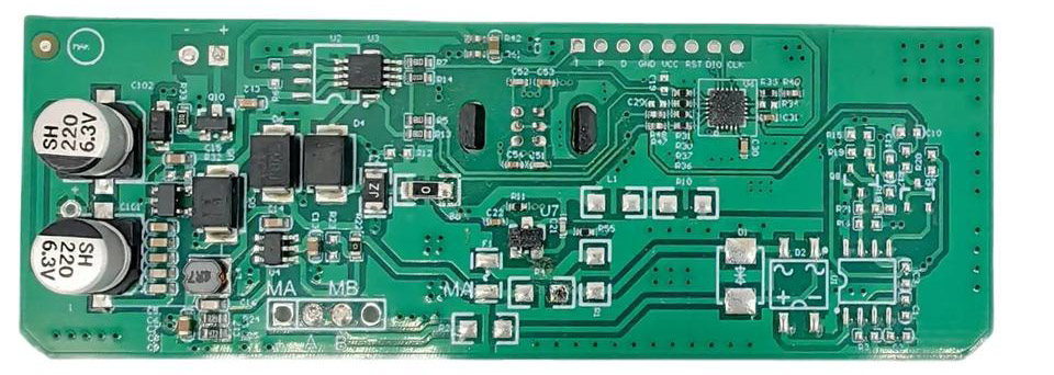
1. One board, three core functions
Metering module: signal acquisition and calculation. Display module: visual readout for end users. Sensing module: converts pressure or flow into electrical signals. Typical mainboard configuration: 1.28-inch 240 RGB color screen, 6 mm high-strength magnet, through-hole inductor. PCB: FR4, 1.6 mm, 2-layer, lead-free HASL. Pressure sensing is implemented on a separate sub-board, centered on the MS5837 30BA01-50 24-bit sensor. Sub-board dimension approx. 37.5 × 18.55 mm, also FR4 1.6 mm 2-layer with lead-free HASL.
2. Protect the display screen from crush damage first
The 0.65 mm pitch screen requires tight alignment for post-soldering; minor misalignment causes cold joints or bridging. Adjust pick-and-place and cleaning parameters according to the incoming condition of customer-supplied screens. Conductive foam double-sided adhesive is applied to the screen area for cushioning. Buzzer wires are fixed with AB structural adhesive at a 10:1 mixing ratio. Buzzer components are staggered during packaging to prevent collision. Packing specification: ESD bag + multi-layer divider and flat card, 150 PCS per inner box, 600 PCS per carton. A clearance of approx. 30 mm is reserved around the pallet before wooden framing. Most screen crush defects occur during packaging and transit, not at SMT stage. Rule: Screen alternatives require written customer approval. Screens of identical size but different part numbers may differ in interface definition and timing; unauthorized substitution leads to full-batch rework.
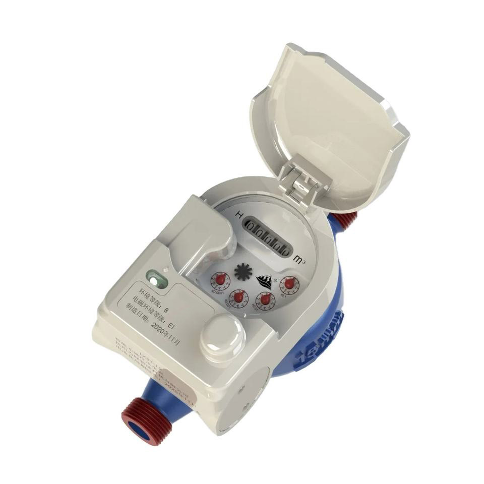
3. MS5837 sensing sub-board: high precision on a small form factor
The 24-bit resolution is highly sensitive to soldering quality and cavity cleanliness. Stencil aperture and solder volume must be tightly controlled to ensure flat, well-aligned pads. Assembly includes spring-loaded pogo pins, brass gold-plated 4-pin terminals and M3 SMT round nuts. The spring travel of pogo pins governs contact reliability, while the gold plating of terminals determines contact resistance after repeated mating cycles. Critical note: The sensor cavity must not be contaminated by conformal coating or flux. If the sensing diaphragm is sealed off, readings will drift.
4. Magnets and through-hole components: mistake-proof assembly outweighs pure process control
The 6 mm high-strength magnet is used for triggering or positioning. Reversed polarity does not trigger an immediate failure but causes abnormal operation of the complete device. Polarity mistake-proofing is built into the fixture, and adsorption direction is sampled after assembly. For through-hole inductors and other DIP parts, pin length and lead trimming consistency are controlled to avoid cold solder joints and tilted components.
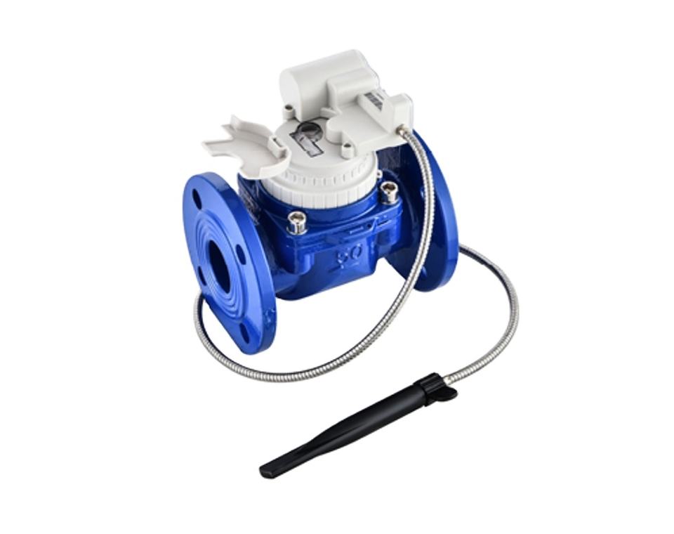
5. Process sequence cannot be arbitrarily adjusted
Standard flow: double-sided SMT → firmware programming → DIP → sub-assembly → functional test → packaging. The position of programming relative to DIP depends on customer firmware and validation criteria. Once finalized, the sequence must follow the controlled document. No mixed-lot operation across process stages. Mixing batches with different firmware versions or different screen models results in mass misassembly.
6. Protection and cleaning selected according to application environment
Boards for humid or outdoor deployment receive conformal coating. Fluorescent types such as RC-2087A are widely adopted for easy coverage inspection under UV light. Coating keep-out zones: mounting holes, connectors, test points, buzzers and SD card sockets must remain uncoated. Two application methods: fixture spraying for consistent mass production; hand brushing for flexible small batches and rework. Boards with strict cleanliness requirements undergo aqueous cleaning before UV conformal coating.
7. Traceability and packaging
QR code labels must be affixed before conformal coating; otherwise the coating layer will block scanning. Labels are placed outside keep-out zones and must not press against the screen surface. Export packaging uses EPE corner protectors and wooden pallets per customer specifications.
8. Common pitfalls
- Screen crush damage during packing and transportation
- Reversed magnet polarity
- Offset sensor pads or cavity contamination by coating leading to reading drift
- Replacement screens adopted without written customer approval
- Mixed batches with mismatched firmware or screen models
- Barcode applied after conformal coating, losing traceability
9. Checklist
- Are fine-pitch screen alignment and post-soldering parameters locked?
- Are screen cushioning and layered packaging procedures enforced?
- Is MS5837 stencil aperture and cavity cleanliness controlled?
- Are pogo pin and gold-plated terminal assemblies sampled for inspection?
- Is magnet polarity mistake-proofing implemented?
- Is process sequence and batch segregation followed?
- Are conformal coating grade, keep-out areas and curing parameters per controlled documents?
- Are QR labels applied prior to conformal coating?
A well-built flow meter mainboard is not judged by SMT throughput. The real metrics are whether screens stay intact, sensors remain uncontaminated, and magnets are fitted with correct polarity. Stable metering comes from stabilizing these seemingly trivial details.
-
 Rapid Prototyping
Providing comprehensive one-stop PCB service solutions
-
 Payment
Security
Multiple payment channels to ensure customer payment security!
-
 Fast
Delivery
Fastest 8 hours, small batch speed 1-2 days
-
 Quality
Assurance
If the quality does not match the description or has defects, we will refund.


Wechat Support

Scan the QR code to connect with our Wechat support team. You can also visit the Help Center for answers to common questions before reaching out.